
Calibration
The device is supplied fully calibrated, however, if it is necessary to recalibrate keep to
the following instructions.
1: Remove the top cover by unscrewing the 4 fixing screws.
2: Adjust supply voltages -16.5V +16.5V through trimmer R18 R19, (Fig.1),
measure voltages on F3 and F2 fuse holders alongside.
Check the 12,5V voltage on F1 (+ -0.8v).
 Fig.1
3: Adjustment output signal "TO RECORD"
- Send signal 0dBm (0.775v) 1khz in "LINE IN"
- Set control selector to OFF position
- Adjust the TO RECORD output for 0dBm through trimmer R16 (Fig.2)
- Repeat on the other channel
Fig.1
3: Adjustment output signal "TO RECORD"
- Send signal 0dBm (0.775v) 1khz in "LINE IN"
- Set control selector to OFF position
- Adjust the TO RECORD output for 0dBm through trimmer R16 (Fig.2)
- Repeat on the other channel
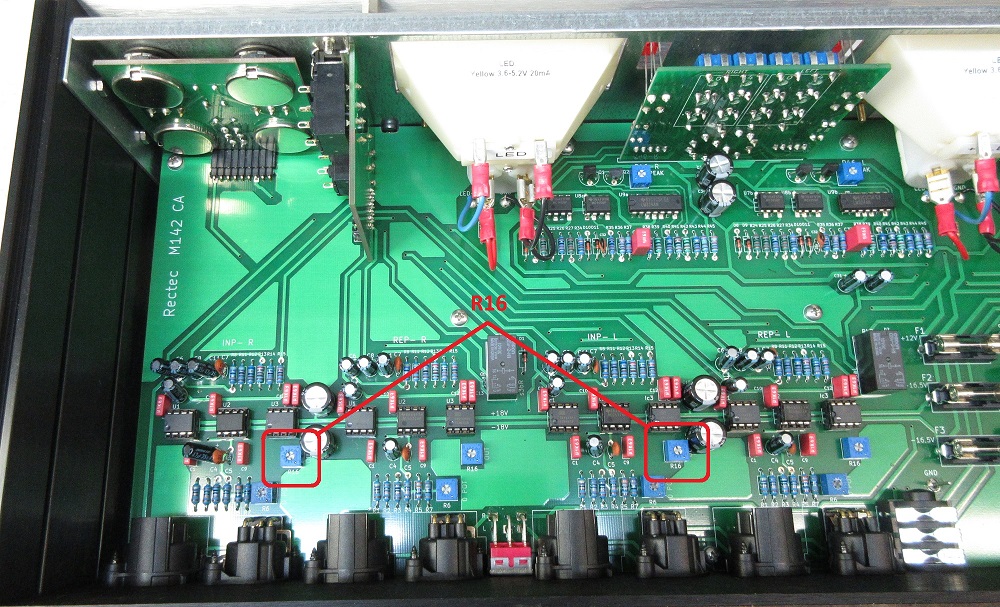 Fig.2
4: Ajustment output control "TO MONITOR"
- Send 0dBm (0.775v) 1khz signal in "FROM RECORD"
- Set control selector to OFF position
- Adjust the TO MONITOR output for 0dBm via R16 (with a 600 hom termination resistor) or
adjust to + 0,8dBm without resistor (Fig.3)
-Repeat on the other channel
Fig.2
4: Ajustment output control "TO MONITOR"
- Send 0dBm (0.775v) 1khz signal in "FROM RECORD"
- Set control selector to OFF position
- Adjust the TO MONITOR output for 0dBm via R16 (with a 600 hom termination resistor) or
adjust to + 0,8dBm without resistor (Fig.3)
-Repeat on the other channel
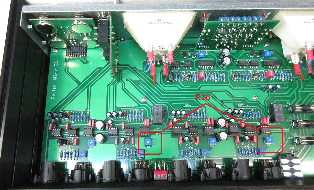 Fig.3
Adjustment 0 potentiometers
5: Ajustment output signal "TO RECORD"
- Set control selector to On position
- Set the INPUT volume control potentiometer to 0
- Send signal 0dBm (0.775v) 1khz in "LINE IN"
- Adjust the TO RECORD output for 0dBm via the trimmer R6 (Fig.4)
- Repeat on the other channel
Fig.3
Adjustment 0 potentiometers
5: Ajustment output signal "TO RECORD"
- Set control selector to On position
- Set the INPUT volume control potentiometer to 0
- Send signal 0dBm (0.775v) 1khz in "LINE IN"
- Adjust the TO RECORD output for 0dBm via the trimmer R6 (Fig.4)
- Repeat on the other channel
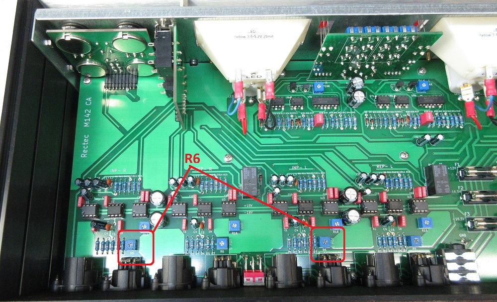 Fig.4
6: Ajustment output control "TO MONITOR"
- Set control selector to On position
- Set the REPRO volume adjustment potentiometer to 0
- Send 0dBm (0.775v) 1khz signal in "FROM RECORD"
- Adjust the TO MONITOR output for 0dBm via R6 (with a 600 hom termination resistor) or
adjust to + 0,8dBm without resistor (Fig.5)
-Repeat on the other channel
Fig.4
6: Ajustment output control "TO MONITOR"
- Set control selector to On position
- Set the REPRO volume adjustment potentiometer to 0
- Send 0dBm (0.775v) 1khz signal in "FROM RECORD"
- Adjust the TO MONITOR output for 0dBm via R6 (with a 600 hom termination resistor) or
adjust to + 0,8dBm without resistor (Fig.5)
-Repeat on the other channel
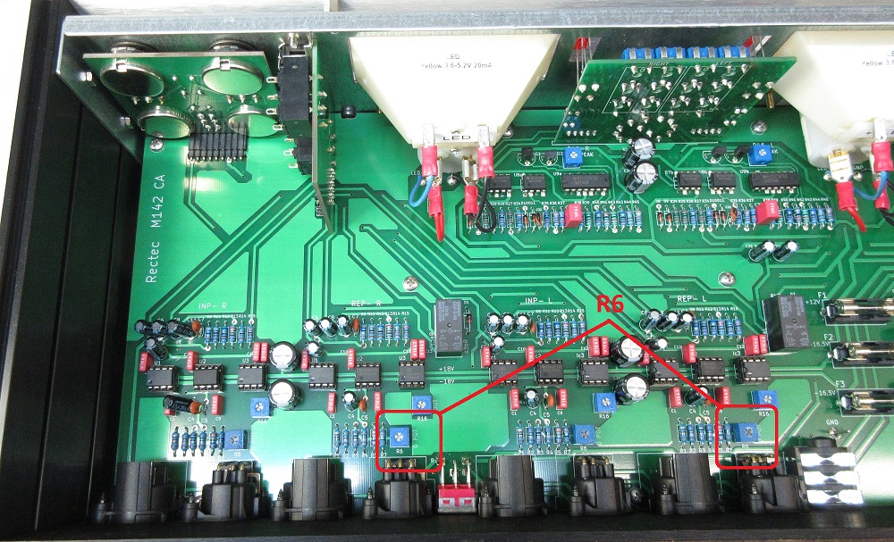 Fig.5
7: VU meter adjustment
-Set volume control selector to OFF
-Set the dBu / 0VU switch to "0"
-Set the "INPUT / REPRO" selector to INPUT
-Send signal 0dBm in input, adjust VU level for 0 dB via trimmer 0 on trimmer card. (Figure 6)
-Place the dB / 0VU switch in 2
-Increase signal + 2dBm in input, adjust VU level for 0 dB via trimmer 2 .
-Repeat the procedure for the remaining positions 4-6-8-10 by increasing the signal to +4, +6 and so on.
Fig.5
7: VU meter adjustment
-Set volume control selector to OFF
-Set the dBu / 0VU switch to "0"
-Set the "INPUT / REPRO" selector to INPUT
-Send signal 0dBm in input, adjust VU level for 0 dB via trimmer 0 on trimmer card. (Figure 6)
-Place the dB / 0VU switch in 2
-Increase signal + 2dBm in input, adjust VU level for 0 dB via trimmer 2 .
-Repeat the procedure for the remaining positions 4-6-8-10 by increasing the signal to +4, +6 and so on.
 Fig.6
8: Peak led adjustment
-Place the dB / 0VU selector switch to 0
-Send signal + 6dBm in input, adjust the ignition of the led +6 in
so that it turns on when + 6dBm is reached by trimmer R46 (PEAK) on
VU driver section, (Fig.7) check that they light up together.
-Increase the input level up to +8 and check that the +8 LED lights up together
Fig.6
8: Peak led adjustment
-Place the dB / 0VU selector switch to 0
-Send signal + 6dBm in input, adjust the ignition of the led +6 in
so that it turns on when + 6dBm is reached by trimmer R46 (PEAK) on
VU driver section, (Fig.7) check that they light up together.
-Increase the input level up to +8 and check that the +8 LED lights up together
 Fig.7
Fig.7
Rectec - Via Francesco De Pinedo 39 - 47122 Forlì (FC) ITALY